Unlock safety awareness, informed decision-making, and practical clarity with this meticulously structured walkthrough of how electricity travels through your home—from the utility connection to the outlet powering your morning coffee.
Flipping a light switch feels effortless. Behind that simplicity lies a precisely engineered network designed for controlled energy delivery and layered safety. Most homeowners interact with their electrical system only during disruptions—a tripped breaker, a dead outlet, a flickering light. This guide transforms uncertainty into understanding. We’ll trace electricity’s journey through your home using clear analogies, safety-focused protocols, and principles aligned with widely recognized electrical standards. Whether you’re troubleshooting a minor issue, planning a renovation, or seeking greater confidence in your home’s infrastructure, this resource provides actionable knowledge while emphasizing clear boundaries between homeowner-safe actions and licensed professional work. True electrical safety begins with knowing both what you can do and when to call an expert.
Introduction: Why Understanding Your Electrical System Matters
Imagine your home’s electrical system as a circulatory network. Utility lines act as major arteries delivering energy. The main panel functions as the heart, regulating flow and pressure. Branch circuits become smaller vessels distributing power room by room. Outlets, switches, and fixtures represent capillaries where energy performs its work. Just as ignoring subtle bodily cues can escalate into serious health concerns, overlooking electrical warning signs—warm faceplates, buzzing sounds, frequent breaker trips—may indicate conditions requiring attention. Electrical safety organizations consistently identify faulty wiring and outdated components among leading contributors to residential fire risks. Knowledge isn’t about creating anxiety; it’s about cultivating awareness that empowers proactive care.
This guide is structured around foundational safety principles reflected in widely adopted electrical standards. These standards evolve through consensus among engineers, safety experts, inspectors, and manufacturers, incorporating decades of field experience and incident analysis. While local building codes may vary—and always consult your municipal building department—this framework explains the universal logic underpinning safe residential electrical design. We avoid overwhelming jargon, translate technical concepts into relatable analogies, and emphasize why protocols exist. Understanding the reasoning behind a rule makes it memorable and actionable. By the end, you’ll recognize critical warning signs, understand component relationships, and know precisely when a task falls within homeowner scope versus when licensed expertise is essential. This isn’t about performing complex electrical work yourself; it’s about becoming an informed steward of one of your home’s most vital systems.
The Electrical Journey Framework: Tracing Power From Source to Socket
Electricity’s path follows a deliberate, hierarchical sequence designed for control, safety, and efficiency. Visualizing this journey transforms fragmented knowledge into a cohesive mental model. Think of it as a story with distinct chapters: arrival at your property, regulation at the command center, distribution through branch circuits, and final delivery at endpoints. We’ll walk through each stage with technical accuracy balanced by accessible explanation, highlighting safety checkpoints and common points of confusion along the way.
Step 1: The Point of Entry – Where Utility Power Meets Your Property
Before electricity powers a single device, it crosses a critical boundary: the demarcation between the utility company’s infrastructure and your home’s system. This transition occurs differently based on your home’s location and era.
Overhead Service Drop Configuration:
In many suburban and rural areas, power arrives via overhead lines strung between utility poles. The final segment—the service drop—consists of three insulated conductors (two “hot” wires and one neutral) suspended from the nearest pole to your roofline. These connect to a weatherhead: a sealed, upward-angled conduit fitting mounted on the roof or exterior wall. Its angled design prevents rain, snow, or debris from traveling down the conduit. Inside the conduit, wires descend vertically to the meter base. Crucially, the utility owns and maintains everything up to and including the connection point inside your meter socket. Tampering with the weatherhead, service drop cables, or meter base is extremely hazardous and unauthorized. Voltages at this stage remain at utility distribution levels until stepped down near your property. Never attempt to touch, adjust, or inspect these components. If you observe sagging lines, damaged weatherhead casing, or corrosion on the meter base, contact your utility provider immediately.
Underground Service Lateral Configuration:
Newer developments and urban areas often utilize buried service lines. The utility runs cables through a protected conduit from a nearby transformer pad to your property. The conduit emerges near your foundation and connects directly to the meter base, typically mounted lower on an exterior wall. While less vulnerable to weather damage, underground services require careful handling. The conduit exit point must be properly sealed against moisture intrusion. Rodents may occasionally access exposed conduit ends. Before any digging project—even for planting—always call 811 (“Call Before You Dig”) several business days in advance. This free service locates buried utilities to prevent dangerous strikes. As with overhead services, the utility owns the meter and connections up to the load side of the meter socket. Report any suspected meter issues (unusual sounds, visible damage) directly to your provider.
The Meter: Measuring Your Consumption
Positioned between the utility connection and your main panel, the electricity meter precisely measures kilowatt-hours (kWh) flowing into your home. Modern digital smart meters transmit usage data wirelessly, enabling remote readings and customer portal insights. Older electromechanical meters feature a spinning aluminum disc whose rotation speed correlates to power usage—a visible demonstration of electromagnetic principles. While you cannot service the meter itself, understanding its role aids awareness. An unusually rapid disc spin with major appliances off might indicate an internal circuit issue worth investigating. Unusual buzzing, burning smells near the meter, or visible arcing demand immediate utility notification. Never attempt to bypass, tamper with, or remove the meter seal—this is illegal, extremely dangerous due to exposed connections, and carries significant penalties.
Critical Safety Boundary: The space between the utility connection point (weatherhead or underground conduit entry) and the line side of your meter remains energized at utility voltage levels even if your main breaker is switched off. This zone is strictly off-limits to homeowners. Respect this boundary unequivocally.
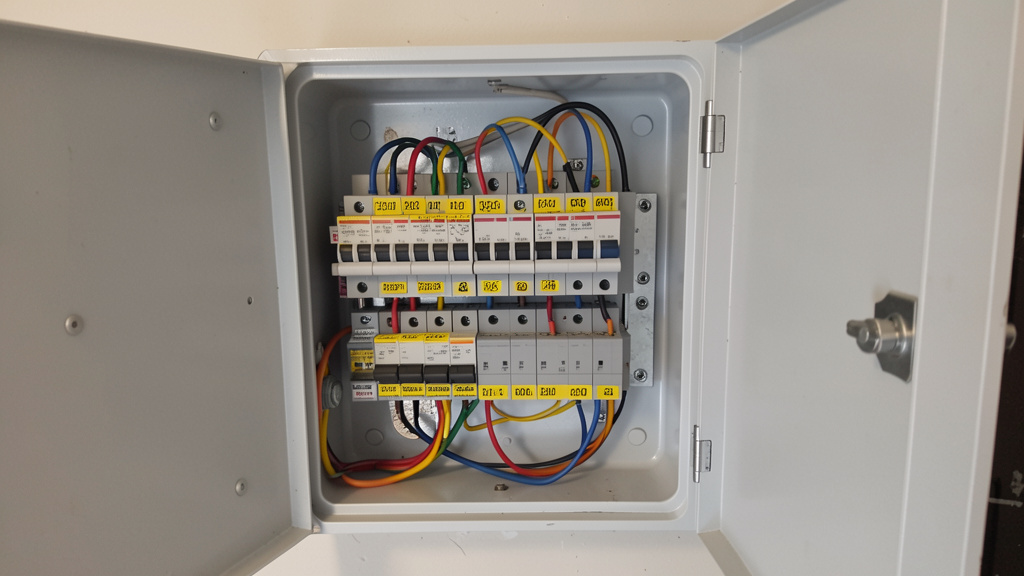
Step 2: The Main Service Panel – Your Home’s Electrical Command Center
Once power passes through the meter, it enters the main service panel (often called the breaker box or load center). This metal enclosure is the absolute nerve center of your home’s electrical system. Here, incoming power is divided, controlled, protected, and grounded before branching to circuits throughout your home. Understanding its components is essential for safe, informed interaction.
Anatomy of a Modern Circuit Breaker Panel:
Main Disconnect Breaker: Located prominently (often top or bottom), this large double-pole breaker (typically rated 100A, 150A, or 200A) controls all power entering the panel. Flipping this switch cuts electricity to every branch circuit. This is the single most important safety control for any major electrical work near the panel. Older fuse-box systems may use a separate pull-out main disconnect block.
* Bus Bars: Hidden behind the breaker mounting rails, these thick copper strips distribute power from the main breaker to individual circuit breakers. The two incoming “hot” service wires connect to the main breaker, which feeds the bus bars. One bus bar supplies breakers on the left column; the other supplies the right. This alternating arrangement enables double-pole breakers (for 240V appliances) to span two adjacent slots across both columns.
* Circuit Breakers: Resettable safety switches protecting individual branch circuits. Breakers monitor current flow. If amperage exceeds the breaker’s rating (e.g., 15A or 20A) for a sustained period (overload) or detects a sudden massive surge (short circuit), the internal mechanism trips, instantly interrupting power. Common types include:
* Standard Thermal-Magnetic: Most prevalent for general lighting and outlet circuits. Thermal element responds to moderate overloads (slow heat buildup); magnetic element responds instantly to short circuits.
* GFCI (Ground Fault Circuit Interrupter): Required in wet/damp locations (kitchens, bathrooms, garages, outdoors, basements). Detects tiny current imbalances (as small as 4–6 milliamps) between hot and neutral—indicating electricity leaking to ground (possibly through a person)—and trips in milliseconds to prevent severe shock.
* AFCI (Arc Fault Circuit Interrupter): Required in most living areas (bedrooms, living rooms, hallways) in homes built or renovated after early 2000s adoption. Detects dangerous “arc faults”—sparking from damaged wire insulation, loose connections, or pinched cords—a leading ignition source for electrical fires. Trips before heat builds to dangerous levels.
* Dual-Function (AFCI/GFCI): Combines both protections, increasingly specified for kitchen countertop and laundry circuits.
* Neutral Bus Bar: Terminal block where all white (neutral) wires from branch circuits terminate. Neutrals provide the normal return path for current back toward the source. In the main panel only, the neutral bus bar is bonded (connected) to the ground bus bar and the grounding electrode system. This single-point bonding is critical for safety but occurs only once in the entire system—at the main service panel.
* Ground Bus Bar: Separate terminal block (bonded to neutral in the main panel) where all bare copper or green (grounding) wires connect. Ground wires provide a dedicated, low-resistance emergency path for fault current to safely trip the breaker. They also link to the home’s grounding electrode system (ground rods, concrete-encased electrode).
* Grounding Electrode Conductor (GEC): A thick bare copper or green-insulated wire running from the ground bus bar to grounding electrodes driven into the earth (typically two 8-foot rods spaced at least 6 feet apart, or a concrete-encased electrode). This connection stabilizes voltage relative to earth and provides a path for lightning strikes or utility surges to dissipate safely.
* Panel Directory/Labeling:* A crucial yet often neglected component. A clear, accurate directory identifying what each breaker controls (e.g., “Kitchen Counter Outlets,” “Master Bedroom Lights,” “Garage Freezer”) prevents dangerous guesswork during emergencies or maintenance. Updating this is one of the safest and most valuable electrical-related tasks a homeowner can perform.
Panel Types and Evolution:
Modern Circuit Breaker Panels (Post-1960s): Brands like Square D (Homeline, QO), Siemens, Eaton (BR, CH), and GE dominate. Generally reliable and support modern safety devices (AFCI, GFCI). Capacity (amp rating) is key: 100A may suffice for very small homes; 150A is common for average homes; 200A is standard for new construction and renovations with higher demand (EV chargers, heat pumps, workshops). Panels rated below 100A often signal an outdated system warranting professional evaluation.
* Fuse Boxes (Pre-1960s): Older homes may have screw-in or cartridge-type fuse panels. While functional if meticulously maintained, they lack resettable convenience and often cannot accommodate modern safety devices like AFCIs. Critically, the temptation to replace a blown 15A fuse with a higher-rated fuse (“overfusing”) creates severe fire risk by allowing wires to overheat before the fuse operates. If you have a fuse box, consult a licensed electrician about evaluation and potential replacement, especially when adding circuits or major appliances.
* Problematic Panels (Critical Safety Note): Two panel types manufactured primarily between the 1950s–1980s pose documented hazards and warrant immediate professional evaluation:
* Federal Pacific Electric (FPE) Stab-Lok: Independent testing and documented incident reports indicate these breakers may fail to trip during overloads or short circuits. Replacement is strongly recommended by safety authorities.
* Zinsco/Sylvania:* These panels suffer from design flaws where breakers can become stuck “on” internally even when the handle is flipped “off,” leaving circuits energized during supposed maintenance. Breakers also degrade internally over time. Replacement is critical.
Interacting Safely with Your Panel:
Before Opening: Stand to the side of the panel, not directly in front. Wear safety glasses. Ensure hands and floor are dry. Use a non-contact voltage tester to confirm the panel cover screws aren’t energized (rare, but possible with internal faults).
* Opening the Cover: Remove only the outer deadfront cover (the labeled faceplate with breaker handles exposed). Do not remove the inner trim or bus bar cover. This inner barrier protects against accidental contact with live bus bars—a lethal hazard even if individual breakers are off. Only qualified personnel should access behind this barrier.
* Resetting a Tripped Breaker: Firmly push the handle to the full OFF position (you may hear/feel a click). Then, push it firmly to the ON position. If it trips immediately again, do not repeatedly reset it. This indicates a persistent fault (short circuit, ground fault, severe overload). Unplug everything on that circuit and try resetting. If it holds, plug devices back in one by one to identify the culprit. If it trips with nothing plugged in, or you smell burning, leave it off and contact a licensed electrician.
* Labeling Your Panel (Safe DIY Task):* With power ON, use a circuit tracer tool (highly recommended) or the “buddy system” (one person at the panel, one flipping switches/plugging in a radio at outlets). Update the directory clearly with a permanent marker or printed labels. Note circuits protected by AFCI or GFCI devices. This small investment prevents future accidents and streamlines troubleshooting.
The Fundamental Principle: The main service panel is not merely a collection of switches; it is a precisely engineered safety ecosystem where overcurrent protection, grounding, and bonding converge to transform raw utility power into a controlled, usable resource. Every component exists to answer one critical question: “If something fails, how do we make it fail safely?”
Step 3: Branch Circuits – The Pathways Distributing Power Through Your Home
Emerging from the panel, electricity travels along branch circuits—dedicated pathways of insulated wires running through walls, floors, and ceilings to deliver power precisely where needed. Understanding circuit design principles is key to safe usage and informed planning.
Circuit Anatomy: The Three Essential Conductors
Every standard branch circuit comprises three distinct wires, each with a critical role and standardized color coding (in North American residential practice):
* Hot Wire (Black, Red, or other non-white/green): Carries voltage (120V or 240V) from the panel to the device (outlet, light, switch). This is the “live” conductor under electrical pressure. Black is standard; red often indicates a second hot in multi-wire circuits or the switched leg in three-way switch setups.
* Neutral Wire (White or Gray): Provides the normal return path for current back to the panel (and ultimately to the utility transformer). Under normal operation, it carries the same current as the hot wire. It connects to the neutral bus bar in the panel. Crucially, neutral is NOT the same as ground, though both terminate on bonded bars in the main panel.
* Ground Wire (Bare Copper or Green): A dedicated safety path only. It carries current only during a fault condition (e.g., a loose hot wire touches a metal appliance chassis). This surge travels instantly down the ground wire, causing the breaker to trip and de-energize the circuit. Ground wires connect all metal boxes, device mounting straps, and appliance frames back to the ground bus bar, ensuring stray voltage has a safe path to trip the breaker—not through a person.
Wire Types, Gauges, and Their Critical Roles
The cable housing these conductors varies by location and application. Wire gauge (thickness) is paramount—it determines the maximum safe current (amperage) the conductor can carry without overheating. Using undersized wire for a circuit’s load is a primary fire hazard.
- NM-B (Non-Metallic Sheathed Cable / “Romex”): Standard for dry, interior residential wiring (inside walls, attics, basements not subject to physical damage). The plastic sheath contains individually insulated hot(s), neutral, and a bare ground wire. Common configurations:
- 14/2 NM-B: 14-gauge wire, two conductors (black, white) + ground. Rated for 15-amp circuits. Found in older general lighting circuits.
- 12/2 NM-B: 12-gauge wire, two conductors + ground. Rated for 20-amp circuits. Current standard for most general-purpose outlet circuits (kitchens, living areas, bedrooms) and dedicated lighting circuits. Handles higher loads safely.
- 12/3 or 14/3 NM-B: Contains black, red, white + ground. Used for three-way switches, multi-wire branch circuits (MWBCs), or 240V circuits requiring a neutral.
- 10/2, 8/2, 6/2 NM-B: Larger gauges for high-demand 240V appliances: 10-gauge for 30A (dryers, some AC units), 8-gauge for 40A (electric ranges), 6-gauge for 50A (large RV outlets, subpanels). Always verify appliance requirements and applicable standards.
- UF-B (Underground Feeder): Features solid, moisture-resistant PVC insulation around each wire and a solid PVC sheath. Rated for direct burial (minimum 24″ depth) or exposed outdoor use. Used for outdoor outlets, landscape lighting, shed feeds. Never substitute NM-B for UF-B outdoors or underground—it degrades rapidly, creating hazards.
- Metal-Clad (MC) Cable or Armored Cable (AC / “BX”): Insulated conductors wrapped in flexible metal armor. Provides superior physical protection. Common in garages, basements subject to damage, or where local code requires it. Requires specific fittings.
- Conduit Systems (EMT, PVC, Rigid): Individual THHN/THWN insulated wires pulled through metal or plastic tubing. Offers maximum protection and flexibility for future changes. Standard in garages, unfinished basements, outdoor exposed runs. Requires significant skill to install properly.
Critical Wire Gauge Reference Guide
| Wire Gauge (AWG) | Typical Cable Type | Max Circuit Ampacity* | Common Residential Applications | Critical Consideration |
|---|---|---|---|---|
| 14 | NM-B, UF-B | 15 Amps | General lighting circuits (older homes) | Never use on a 20A circuit. Overheats dangerously. |
| 12 | NM-B, UF-B | 20 Amps | Standard for modern outlet circuits (kitchen, living areas), dedicated lighting | Minimum safe size for most general-use outlets today. |
| 10 | NM-B, UF-B, THHN | 30 Amps | Electric dryers, window AC units, water heaters, subpanel feeds | Verify appliance nameplate requirements. |
| 8 | NM-B, UF-B, THHN | 40 Amps | Electric ranges/ovens, large air conditioners | Requires double-pole breaker. |
| 6 | NM-B, UF-B, THHN | 55 Amps (often protected at 50A/60A) | Large subpanels, EV chargers (Level 2), welders | Critical for high-demand modern upgrades. |
| 4 | THHN (in conduit) | 70 Amps | Main feeder to subpanels, large workshop feeds | Professional installation strongly recommended. |
| 2/0 | THHN (in conduit) | 100 Amps | Main service entrance (smaller homes), large subpanels | Utility/service entrance work—licensed electrician only. |
*Ampacity values assume standard conditions per widely referenced tables. Derating may apply for multiple wires in conduit, high ambient temperatures, or continuous loads (>3 hours). Always follow applicable electrical standards and local code.
Circuit Design Logic: Dedicated vs. General Purpose
Safety standards mandate specific circuit types to prevent overloads and enhance protection:
* Dedicated Appliance Circuits: High-wattage appliances require their own circuit directly from the panel. Examples:
* Refrigerator: Often recommended on its own 15A or 20A circuit to avoid nuisance trips.
* Microwave: Typically requires a dedicated 20A circuit.
* Dishwasher/Garbage Disposal: May share a 20A circuit via specific wiring, or have dedicated circuits.
* Electric Range/Oven: 40A or 50A 240V circuit.
* Electric Dryer: 30A 240V circuit.
* HVAC Systems: Furnace (15A/20A), Air Handler (20A+), Condenser (20A-60A depending on size).
* Bathroom Receptacles: At least one 20A circuit dedicated only to bathroom outlets (can serve multiple bathrooms, but nothing else).
* Kitchen Countertop Outlets: Two or more 20A circuits dedicated only to countertop outlets (GFCI protected). No lighting or other room outlets allowed. Prevents overloading when using multiple high-wattage appliances.
* General Lighting/Outlet Circuits: Serve multiple outlets and lights in living areas, bedrooms, hallways. Typically 15A (with 14-gauge wire) or preferably 20A (with 12-gauge wire). Modern standards often require AFCI protection. A single circuit might serve 8–10 outlets or lights, but load calculation is essential.
* Multi-Wire Branch Circuits (MWBCs): An efficient but often misunderstood design. Uses a 12/3 or 14/3 cable with two hot wires (black & red, on opposite phases) sharing one neutral wire and one ground wire. Supplies two separate 120V circuits. Critical Safety Rule: MWBCs must be controlled by a double-pole circuit breaker (or two single-pole breakers with a handle tie). This ensures both hots disconnect simultaneously during maintenance. If only one hot is turned off, the shared neutral can still carry current from the other live circuit, creating a severe shock hazard. MWBCs are less common in new construction due to AFCI complexity but prevalent in homes built from the 1970s–1990s. Identify them by cables with red wires entering the panel and handle-tied breakers.
The Non-Negotiable: Junction Boxes
Every point where wires connect—splices, outlets, switches, light fixtures—must be housed within an accessible junction box (plastic or metal). This box contains sparks or heat from a faulty connection, preventing contact with flammable building materials. Never bury a splice inside a wall without a box. Never install a device without securing it to a box. Box fill capacity (maximum wires/devices allowed) is strictly regulated based on box volume and wire gauge—overfilling creates heat buildup and fire risk. This is why adding outlets isn’t always simple; box space and circuit capacity must be verified.
Step 4: The Final Destination – Outlets, Switches, and Fixtures
This is where electricity performs its intended work. Each device type has specific construction, safety features, and installation requirements.
Receptacles (Outlets): Engineered for Safety and Function
Standard Duplex Receptacle (NEMA 5-15R): The common 15A, 125V outlet. Features two vertical slots (neutral wider on the left, hot narrower on the right) and a round ground hole. Internally, brass screws connect to hot wires, silver screws to neutral, green screw to ground. Tabs between top and bottom outlets can be broken to create split-wired configurations.
* Tamper-Resistant (TR) Receptacles: Required in all new residential construction and renovations in many regions since approximately 2008. Feature spring-loaded shutters that open only when equal pressure is applied to both slots simultaneously (as a plug does). Prevents children from inserting foreign objects. Identified by “TR” stamped on the face. Highly recommended for replacement in older homes with young children.
* Weather-Resistant (WR) Receptacles: Required for all outdoor, damp, and wet locations (even under covers). Constructed with corrosion-resistant materials (nickel-plated contacts, UV-resistant thermoplastic). Identified by “WR” stamp. Always use WR-rated GFCI receptacles outdoors.
* GFCI Receptacles: Identified by “TEST” and “RESET” buttons. Continuously compare current flow on hot and neutral. A difference >5mA triggers a trip. Critical Locations: All bathroom outlets, kitchen countertop outlets, garage outlets (except ceiling-mounted for openers), unfinished basement outlets, crawl spaces, outdoor outlets, within 6 feet of sinks. Testing Protocol: Press TEST monthly (should click and cut power). Press RESET to restore. If it won’t reset or fails to trip when tested, replace immediately. GFCIs have a functional lifespan (typically 10–15 years).
* 240V Receptacles (NEMA Configurations): Used for large appliances. Common types:
* NEMA 6-20R: 20A, 240V (no neutral). For some air conditioners, welders.
* NEMA 10-30R: 30A, 125/250V (hot-hot-neutral, no ground). Obsolete and unsafe. Found on older dryers/ranges. Lacks dedicated ground. Requires replacement with modern NEMA 14-30R during appliance upgrade. Never remove the ground pin from a modern appliance cord to fit this outlet.
* NEMA 14-30R: 30A, 125/250V (hot-hot-neutral-ground). Modern standard for electric dryers.
* NEMA 14-50R:* 50A, 125/250V. Standard for electric ranges/ovens, RV park outlets, Level 2 EV chargers.
Switches: Controlling the Flow
Single-Pole Switch: Most common. Controls a light or outlet from one location. Interrupts the hot wire only.
* Three-Way Switch: Allows control of a light from two locations (e.g., top and bottom of stairs). Uses two three-way switches and a 3-wire cable (black, red, white + ground) between them. The white wire in this cable functions as a “traveler” (hot) and must be re-identified with black tape at both ends to avoid confusion with neutral. A common point of wiring errors.
* Four-Way Switch: Used between two three-way switches to enable control from three or more locations. Has four terminals (plus ground). Requires precise wiring sequence.
* Dimmer Switches: Allow light level adjustment. Critical Compatibility: Must match bulb type (incandescent/halogen, LED, CFL) and total fixture wattage. Using an incandescent-only dimmer with LED bulbs causes flickering, buzzing, or premature failure. Look for “LED Compatible” dimmers and verify maximum wattage rating.
* Smart Switches:* Typically require a neutral wire connection (in addition to hot, load, and ground) to power internal electronics. Many older switch boxes (especially pre-1980s) lack a neutral wire at the switch location, making installation impossible without new cable. Verify box contents before purchasing.
Lighting Fixtures and Hardwired Devices
From simple ceiling boxes to complex fixtures, all connect via wire nuts inside a junction box. Key considerations:
* Box Support: Ceiling boxes for light fixtures must be rated for the fixture’s weight. Fan-rated boxes (marked “For Ceiling Fan Support”) have reinforced brackets to handle vibration and weight (typically 35–50 lbs minimum). Never mount a ceiling fan to a standard plastic light box—it will fail.
* Heat Management: Recessed “can” lights require specific IC (Insulation Contact) or Non-IC rated housings depending on whether insulation contacts the fixture. Using a Non-IC can where insulation is present creates a fire hazard. Modern LED retrofits generate less heat, but housing rating must still be respected.
* Grounding: All metal fixture bodies must connect to the circuit ground wire. This ensures if a hot wire contacts the metal housing, the ground path trips the breaker instantly. Plastic fixtures may not require body grounding, but the circuit ground wire must still be spliced securely inside the box.
The Fundamental Principle: Load Calculation and Circuit Design Logic
Why can’t you safely plug a space heater, microwave, and hairdryer into the same power strip on a bedroom circuit? Why do kitchens require multiple dedicated circuits? The answer lies in electrical load management—the engineering practice of ensuring total demand on a circuit never exceeds its safe capacity. This isn’t arbitrary; it’s physics-based fire prevention.
The 80% Rule: The Essential Safety Margin
Electrical standards mandate that continuous loads (operating for 3 hours or more) must not exceed 80% of a circuit’s rated capacity. This accounts for heat buildup in wires and connections over time. For a standard 15A circuit: 15A × 0.8 = 12A maximum continuous load. For a 20A circuit: 20A × 0.8 = 16A. This is why a 1500W space heater (1500W / 120V = 12.5A) operates near the limit of a 15A circuit and is strongly recommended for a dedicated 20A circuit (12.5A is well under the 16A continuous limit).
Real-World Load Calculation Example: Kitchen Countertop Circuit
Consider a typical kitchen counter circuit (20A, 12-gauge wire):
* Microwave: 1200W (10A)
* Toaster Oven: 1500W (12.5A)
* Coffee Maker: 900W (7.5A)
* Blender: 400W (3.3A)
Running the microwave and toaster oven simultaneously: 10A + 12.5A = 22.5A. This exceeds the circuit’s 20A rating and the 16A continuous limit. Result? The breaker trips—safely interrupting the overload before wires overheat. This is the system working exactly as designed. Standards require two separate 20A circuits for kitchen countertops precisely to distribute these high-wattage appliances. Plugging the microwave into Circuit A and the toaster into Circuit B keeps each circuit within safe limits.
Performing a Basic Room Load Assessment (Homeowner-Friendly):
1. Identify the Circuit: Turn off the suspected breaker. Note all outlets, lights, and fixed appliances that lose power. This defines the circuit’s scope.
2. List Connected Loads: For each device typically used on this circuit, find its wattage (W) on the nameplate or manual. If only amperage (A) is listed: Watts = Amps × Volts (120V for standard circuits).
3. Calculate Typical Simultaneous Load: Add wattages of devices likely to run at the same time. For continuous loads (like a refrigerator compressor), apply the 80% rule mentally: a 700W fridge (5.8A) is acceptable on a 15A circuit alone but leaves little room for other continuous loads.
4. Compare to Circuit Capacity:
* 15A Circuit Max Continuous Load: 15A × 120V × 0.8 = 1,440 Watts
* 20A Circuit Max Continuous Load: 20A × 120V × 0.8 = 1,920 Watts
5. Interpret: If your typical simultaneous load approaches or exceeds these values, you’re overloading the circuit. Solutions: redistribute devices to other circuits, avoid running high-wattage devices together, or (with professional help) add a new dedicated circuit.
Why This Matters Beyond Tripped Breakers:
Repeatedly overloading a circuit—even if the breaker trips “safely”—causes cumulative damage. Heat generated at connection points (outlet screws, wire nuts, breaker terminals) oxidizes metal, increasing resistance. Higher resistance generates more heat during subsequent use, creating a dangerous cycle. This “high-resistance connection” can eventually fail catastrophically, causing arcing, melting insulation, and fire—without tripping the breaker. Nuisance tripping is a critical warning sign, not just an inconvenience. It indicates the circuit is being stressed beyond its design limits. Respecting load calculations interrupts the chain of events that can lead to electrical fires.
Essential Safety Protocols: Non-Negotiable Rules for Any Electrical Interaction
Electricity demands respect, not fear. Adherence to these protocols transforms potentially hazardous interactions into controlled, safe procedures. These rules are non-negotiable, regardless of perceived simplicity.
The Golden Rule: Verify De-Energization
Never assume a circuit is dead. Human error (mislabeling panels), faulty breakers, or backfed voltage (from generators, solar systems, or MWBCs) can leave wires energized even when the correct breaker is off.
1. Shut Off at Source: Turn off the circuit breaker (or remove the fuse) at the main panel. For added safety on the circuit you’re working on, also turn off the main breaker.
2. Test Before Touch: Use a reliable non-contact voltage tester (NCVT) first. Hold it near the wires/outlet slots before touching anything. A beep/light indicates voltage is present—STOP. However, NCVTs can give false negatives due to low battery, user error, or shielded wires.
3. Confirm with Multimeter/Solenoid Tester: For absolute certainty, use a digital multimeter (set to AC voltage) or a solenoid-style tester. Place probes across hot-neutral and hot-ground. Zero volts must be confirmed on both measurements. This two-step verification (NCVT + contact tester) is the professional standard. Test the tester on a known live circuit first to confirm it’s working.
4. Re-Test Frequently: Re-check for voltage after any significant movement, before touching conductors, and after completing work before restoring power. Conditions can change.
Personal Protective Equipment (PPE) and Workspace Safety
Insulated Tools: Always use tools with VDE-rated (or equivalent) insulated handles rated for the voltage (e.g., 1000V). Standard hardware store tools offer minimal protection.
* Safety Glasses: Essential. Arc flashes can eject particles.
* Dry Conditions Only: Never work on electrical components with wet hands, standing on a wet floor, or in damp locations unless using GFCI-protected tools and the circuit is verified dead. Water drastically reduces skin resistance.
* One Hand Rule: When absolutely necessary to take measurements on live circuits (e.g., diagnosing a panel issue with main power on—not recommended for homeowners), keep one hand behind your back. This prevents current from passing across your chest/heart if you accidentally contact two points at different voltages.
* Clear Workspace: Ensure the area around the panel or work site is uncluttered, well-lit, and free of flammable materials. Have a Class C (electrical fire) fire extinguisher accessible.
* Work with a Buddy:* Especially when working near the main panel or on higher-voltage circuits. A second person can cut power or provide assistance in an emergency.
Responding to Electrical Emergencies
Electrical Shock: DO NOT TOUCH THE PERSON while they contact the source. You will become the next victim. Immediately shut off power at the main breaker if safely reachable within seconds. If not, use a non-conductive object (dry wooden broom handle, rubber mat, heavy dry rope) to push or pull the victim away. Call 911 immediately. Begin CPR if trained and the person is unresponsive. Seek medical attention even if conscious—internal injuries may not be apparent.
* Electrical Fire: NEVER use water. Water conducts electricity and can spread fire or cause electrocution. Shut off power at the main breaker only if you can do so safely without approaching the fire. Use a Class C fire extinguisher aimed at the base of the flames. If the fire is in an appliance and you can safely unplug it without getting close to flames, do so—but only if the plug is accessible and dry. Evacuate immediately and call 911 if the fire grows beyond a small contained area.
* Burning Smell / Arcing Sound from Panel: Evacuate the area. Shut off the main breaker only if you can do so safely from a distance* (some panels have an external main disconnect). Call the fire department and your utility company. Do not re-energize the circuit.
The Hierarchy of Safety: When to Stop and Call a Professional
Your safety is infinitely more valuable than any DIY project. Immediately stop and contact a licensed electrician if you encounter:
* Any sign of fire damage: melted insulation, scorch marks on outlets/switches/panel, discoloration on wall plates.
* Buzzing, sizzling, or popping sounds from outlets, switches, or the panel (beyond normal breaker operation).
* Warm or hot faceplates on outlets or switches (beyond slight warmth from high-load devices like chargers).
* Frequent or unexplained breaker tripping (more than occasional overload).
* Flickering or dimming lights correlating with appliance cycling (e.g., lights dim when AC kicks on—could indicate loose service connection).
* Any work involving the main service entrance (meter base, weatherhead, main disconnect), panel replacement, or adding new circuits from the panel.
* Aluminum wiring concerns (see Special Considerations section).
* Uncertainty. If you are unsure about any step, procedure, or observation, stop. Call a professional. There is no shame in prioritizing safety.
Decoding Components: A Visual Guide to Wires, Breakers, and Safety Devices
Moving beyond theory, let’s translate component identification into actionable knowledge. Recognizing what you see empowers informed decisions and clearer communication with professionals.
Wire Identification Deep Dive
Beyond color coding, physical characteristics reveal critical information:
* NM-B Cable Jacket Markings: Look closely at the plastic sheath. Text like “12/2 WG TYPE NM-B 600V E34567 UL” decodes as:
* 12/2: 12-gauge conductors, 2 current-carrying wires (plus ground).
* WG: With Ground.
* TYPE NM-B: Non-Metallic sheathed cable, Building wire.
* 600V: Voltage rating.
* E34567: UL file number (verifies safety certification).
* UL: Underwriters Laboratories mark. Never use cable without a recognized safety listing mark (UL, ETL, CSA).
* Individual Conductor Markings (THHN/THWN): Wires inside conduit have printing: “12 AWG THHN/THWN-2 CU 90°C” means:
* 12 AWG: American Wire Gauge size.
* THHN/THWN-2: Dual-rated for heat and moisture resistance.
* CU: Copper conductor (AL would be aluminum).
* 90°C: Maximum operating temperature. Circuit ampacity is often limited by the termination rating (usually 60°C or 75°C for devices), not the wire’s 90°C rating. Always follow applicable standards.
* Aluminum Wire Identification: Primarily found in homes built 1965–1973. Solid conductors (not stranded) in NM cable. Jacket may say “AL” or “Aluminum.” Individual wires have “AL” printed on insulation. Critical: Aluminum expands/contracts more than copper with heating/cooling cycles, leading to loose connections at outlets/switches over time—a documented fire hazard requiring special remediation (see Special Considerations).
Breaker Identification and Compatibility
Breakers are not universal. Installing the wrong brand/type can cause failure to trip or panel damage.
* Panel Labeling is Authoritative: Open your panel door. A label (usually near the top or inside the door) lists exactly which breaker types are UL-listed for that specific panel. Example: “Use Type QO breakers only” (Square D QO panel). This label overrides any store suggestion or online advice. Using an unlisted breaker voids safety certifications and may affect insurance coverage.
* Physical Keying: Modern breakers have unique slot patterns. A Square D Homeline breaker won’t physically fit into a Siemens panel. However, counterfeit breakers may allow incorrect insertion—always verify against the panel label.
* Counterfeit Breaker Danger: Shockingly common online and in some discount stores. Counterfeits may look identical but lack proper internal components. Purchase breakers only from authorized dealers (electrical supply houses, reputable home centers). Check for crisp UL mark, correct weight, and smooth operation. When in doubt, buy from the panel manufacturer directly.
GFCI and AFCI: Understanding Protection Scope
GFCI Protection Methods:
* GFCI Circuit Breaker: Protects the entire branch circuit—every outlet, switch, and fixture downstream. Ideal for protecting multiple outlets (e.g., all garage outlets) or hard-to-access outlets. More expensive per circuit but centralized reset location (at panel).
* GFCI Receptacle: Protects itself and any standard receptacles wired downstream from its “LOAD” terminals. Most common solution. Requires accessible reset location (at the outlet). Test monthly.
* GFCI Deadfront: A GFCI device with no receptacle slots, only TEST/RESET buttons. Used to protect downstream circuits where an outlet isn’t needed (e.g., protecting a whirlpool tub motor). Often installed near the tub or in a garage.
* AFCI Protection Evolution:
* Combination AFCI (Current Standard): Detects both parallel arcing (hot-to-neutral faults) and series arcing (loose connections in a single wire). Required by modern standards for most 15A/20A branch circuits in living areas. Look for “COMBO” or “Combination Type” on the breaker.
* AFCI Nuisance Tripping: Can be triggered by certain devices: older dimmer switches, some LED drivers, vacuum cleaners. Solutions: Ensure tight connections, use AFCI-compatible dimmers/bulbs, plug problematic devices into a quality surge-protecting power strip (sometimes filters noise), or consult an electrician. Never disable AFCI protection by replacing with a standard breaker.*
Outlet Internals: What Happens When You Plug In
Peering inside a standard duplex receptacle reveals engineering details:
* Contact Wipes: Spring-loaded brass contacts grip plug prongs. Over time, repeated insertion weakens spring tension, leading to loose plugs that arc and generate heat. Replace outlets where plugs feel loose or fall out.
* Screw Terminals vs. Push-In (“Backstab”) Holes: Screw terminals (wrapping wire clockwise around brass/silver screws) create secure, reliable connections preferred by professionals. Push-in holes use a spring clip prone to loosening over time due to thermal cycling and vibration, creating fire risk. Best Practice: Always use screw terminals. If replacing an outlet wired with backstabs, cut the wires and re-terminate on screws. Never reuse backstab holes.
* Breakaway Tabs: Small metal tabs connecting top and bottom outlets on hot (brass) and neutral (silver) sides. Breaking the hot-side tab allows one outlet to be switched while the other remains always hot. Breaking both tabs creates a split-wired receptacle for MWBCs. Tabs must be broken only when the wiring design specifically requires it.
Troubleshooting Common Electrical Issues: A Methodical Diagnostic Approach
Effective troubleshooting is systematic, not random. Start simple, verify assumptions, and isolate variables. Always prioritize safety—de-energize before inspecting or handling components.
Issue 1: Dead Outlet (No Power)
Step 1: Check the Obvious. Test the appliance elsewhere. Try a different lamp/charger in the dead outlet. Check if a wall switch controls the outlet (common in living rooms).
* Step 2: Check GFCI Outlets. A tripped GFCI upstream can kill power to multiple downstream outlets. Check all GFCIs in the house (bathrooms, kitchen, garage, exterior, basement). Press RESET firmly. If it won’t reset, the GFCI itself may be faulty or there’s a fault on the protected circuit.
* Step 3: Check the Panel. Look for a tripped breaker. It may not be fully OFF—look for a handle slightly offset or a red indicator window. Reset firmly (OFF then ON). If it trips again immediately, stop—see “Breaker Trips Immediately” below.
* Step 4: Check Other Outlets on the Circuit. If multiple outlets are dead, it confirms a circuit-level issue. If only one outlet is dead, the problem is likely localized to that outlet or the cable feeding it.
* Step 5: Inspect the Outlet (POWER OFF!). Turn off the breaker. Remove the faceplate and outlet. Check for:
* Loose wires on screw terminals (tighten or re-terminate on screws).
* Burnt/melted insulation or discolored terminals (replace outlet immediately; investigate cause).
* Broken tabs where not intended (reconnect wires appropriately or replace outlet).
* Step 6: Check the Next Outlet Upstream. Power often flows from one outlet to the next. The problem might be a loose connection in the last working outlet* before the dead ones. Inspect that outlet carefully (POWER OFF!).
Issue 2: Circuit Breaker Trips Repeatedly
Pattern Recognition is Key:
* Trips Immediately on Reset (with nothing plugged in): Indicates a dead short or ground fault. A hot wire is likely touching neutral or ground somewhere on the circuit. Do not keep resetting. Leave breaker off. Unplug everything on the circuit. If it still trips immediately, the fault is in the fixed wiring. Call an electrician. If it holds with everything unplugged, plug devices back in one by one to identify the faulty appliance.
* Trips After Several Minutes of Use: Indicates an overload. Too many devices are drawing power simultaneously. Identify high-wattage devices on the circuit. Redistribute loads to other circuits. Avoid daisy-chaining power strips. If overloads happen frequently with normal usage, the circuit may be undersized—a candidate for adding a new circuit (professional job).
* Trips Intermittently / Randomly: Often points to a loose connection* (high-resistance fault) causing arcing. This is a serious fire hazard. Common locations: backstabbed wires in outlets, loose breaker terminal screws, loose neutral/ground connections in the panel. Also common with failing motors or AFCI/GFCI nuisance tripping. Inspect accessible connections (POWER OFF!). If no obvious cause, consult an electrician—intermittent faults are dangerous and hard to diagnose.
Issue 3: Flickering or Dimming Lights
When it Happens:
* Flickers Briefly When AC/Furnace Starts: Often normal due to momentary voltage drop from high inrush current. If severe (lights dim significantly), could indicate an undersized service, loose main connection, or failing compressor—worth having an electrician check the main lugs and service connections.
* Flickers Consistently with No Appliance Cycling: Points to a loose connection somewhere on the circuit—most commonly at the bulb socket (try tightening bulb, replacing socket if corroded), the light switch, or the first outlet on the circuit. Less commonly, a loose neutral connection in the panel (a critical issue requiring immediate professional attention—can cause voltage fluctuations throughout the house).
* Flickers Only on One Circuit: Isolate to that circuit. Check all outlets, switches, and fixtures on the circuit for loose connections (POWER OFF!).
* Flickers Throughout the Entire House: Stop. This strongly suggests a loose service connection before* your main panel—either at the meter socket, the utility’s weatherhead/service drop, or the main lugs inside your panel. This is extremely hazardous and requires immediate attention from your utility company (for connections up to the meter) and/or a licensed electrician (for connections inside the meter base or panel). Do not delay.
Issue 4: Warm or Hot Outlet/Switch Faceplate
Immediate Action: Unplug everything from the outlet. Turn off the circuit breaker. Do not use the outlet/switch.
* Cause: Almost always a loose connection creating high resistance. Current flowing through resistance generates heat (P = I²R). This is a progressive failure mode—heat oxidizes the connection, increasing resistance further, generating more heat. Can lead to melting, arcing, and fire.
* Investigation (POWER OFF!): Remove faceplate and device. Inspect wires for discoloration, melting, or burnt smell. Check tightness of all screw terminals. If any damage is visible, replace the outlet/switch and* cut back damaged wire to fresh copper before re-terminating. If connections look tight but the device was hot, replace the device anyway—internal contacts may be degraded. If the problem recurs after replacement, the fault may be upstream or in the panel—call an electrician.
Issue 5: Buzzing or Humming from Outlet, Switch, or Panel
Outlet/Switch Buzz: Usually indicates arcing from a loose connection or failing device. Turn off power, inspect/replace as above. Can also be caused by dimmer switches interacting with incompatible bulbs (try different bulbs).
* Panel Buzz: A faint hum under heavy load is sometimes normal. A loud, persistent buzz, sizzle, or crackle is dangerous. Could indicate a loose main connection, failing breaker, or arcing bus bar. Turn off the main breaker immediately if safe to do so. Evacuate the area. Call an electrician and your utility company.* Do not open the panel cover.
When to Call a Professional Electrician: Recognizing the Limits of DIY
Confidence is valuable; overconfidence is hazardous. Knowing precisely where homeowner actions end and professional expertise begins is a hallmark of responsible stewardship. This section provides clear, actionable boundaries.
Absolute “Call a Pro Immediately” Scenarios (Do Not Delay):
Visible Damage or Fire Signs: Any scorch marks, melted plastic, discoloration (brown/black) on outlets, switches, faceplates, or inside the panel. Smell of burning plastic or ozone near electrical components. Visible sparks or arcing.
* Panel Issues: Buzzing, sizzling, or crackling sounds from the panel. Warm/hot panel cover. Rust or corrosion inside the panel (indicates moisture intrusion). Any issue with the main breaker or service connections. Presence of Federal Pacific (FPE) Stab-Lok or Zinsco/Sylvania panels (replacement is critical).
* Whole-House Electrical Problems: Frequent tripping of the main breaker. Lights dimming/flickering throughout the entire house consistently. Repeated blown fuses or tripped breakers with no identifiable appliance cause.
* Water and Electricity Mix: Any electrical component submerged in water (flooded basement), exposed to significant leaks, or located where water intrusion is ongoing. Do not touch—shut off main power if safe, then call a pro.
* Aluminum Wiring Concerns: Homes built 1965–1973 with solid aluminum branch circuit wiring require specialized evaluation and remediation. Do not attempt standard outlet/switch replacements.
* Service Upgrades or New Circuits:* Adding a subpanel, upgrading main service (e.g., 100A to 200A), installing new circuits from the panel (kitchen remodel, workshop, EV charger), or any work involving the meter base, weatherhead, or service entrance cables. These require permits, inspections, and utility coordination.
Projects Where Professional Help is Strongly Recommended:
Replacing the Main Electrical Panel: Involves working near live main service conductors (extremely high risk), utility disconnect/reconnect procedures, complex load calculations, and strict code compliance. Insurance implications are significant. Not a DIY project.
* Installing Major Appliances: Electric ranges, dryers, HVAC systems, tankless water heaters. Requires correct circuit sizing, proper receptacle/plug configuration, and verification of appliance grounding. Mistakes can damage appliances or create hazards.
* Whole-Room Rewiring or Major Renovations: Opening walls provides opportunity but also complexity—ensuring correct circuit counts, AFCI/GFCI placement, box fill calculations, and adherence to current standards for new work. An electrician ensures work passes inspection and integrates safely.
* Troubleshooting Intermittent or Complex Faults:* If basic troubleshooting doesn’t resolve the issue, or the problem is elusive (intermittent tripping, random flickering), professional diagnostic tools (circuit tracers, thermal cameras) and experience are invaluable. Guessing can be dangerous.
How to Choose a Qualified Electrician:
1. Verify Licensing and Insurance: Ask for their state/local electrical license number. Verify it with your city/county building department. Confirm they carry liability insurance and workers’ compensation (protects you if an employee is injured). Never hire an unlicensed “handyman” for electrical work.
2. Check References and Reviews: Ask for 2–3 recent references for similar projects. Check BBB, Google Reviews. Look for consistent mentions of cleanliness, communication, and code compliance—not just low price.
3. Get Detailed Written Estimates: Avoid vague quotes. A good estimate specifies: scope of work, materials (brand/type of panel, wire, devices), labor cost, permit fees (who pulls them?), timeline, and warranty. Compare apples-to-apples.
4. Ask About Code Compliance: “Will this work be done to current electrical standards and local amendments?” “Will you obtain the necessary permits and schedule inspections?” Legitimate electricians welcome this question. Avoid anyone who says “permits aren’t needed” for panel work or new circuits.
5. Trust Your Gut: Choose someone who listens to your concerns, explains things clearly without condescension, and makes you feel comfortable. Electrical work happens inside your walls. Professionalism and communication matter.
The Value of a Professional Safety Inspection:
Consider scheduling a whole-house electrical safety inspection if:
* Your home is over 40 years old.
* You’ve recently purchased an older home.
* You notice multiple minor issues (occasional tripping, warm outlets in different locations).
* You’re planning major renovations.
* You have concerns about aluminum wiring or an outdated panel.
A licensed electrician will systematically evaluate your panel, grounding, GFCI/AFCI coverage, outlet/switch conditions, and wiring integrity, providing a prioritized report of findings and recommendations. This investment provides immense peace of mind and a roadmap for necessary upgrades.
Special Considerations for Older Homes: Navigating Legacy Systems Safely
Homes built before 1980 often contain electrical systems that, while functional when installed, no longer meet modern safety expectations or power demands. Understanding these legacy elements is crucial for safe occupancy and informed upgrades.
Knob-and-Tube Wiring (Pre-1940s):
Identification: Ceramic knobs nailed to framing support individual insulated wires (hot and neutral run separately). Ceramic tubes protect wires where they pass through studs/joists. No ground wire. Cloth or rubber insulation (often brittle, cracked, or missing).
* Risks: Lack of grounding (incompatible with modern 3-prong plugs without unsafe adapters), insulation degradation exposing live wires, inability to handle modern loads (typically fused at 15A per circuit), fire hazard if covered by insulation (traps heat), and frequent modifications over decades.
* Safety Protocol: Do not disturb. Avoid driving nails/screws near suspected locations. Have a licensed electrician evaluate. Complete replacement is strongly recommended*, especially if insulation is degraded, circuits are overloaded, or you plan renovations. Partial fixes are often unsafe and not cost-effective long-term. If retained temporarily, ensure circuits are protected by AFCI breakers (where compatible) and use GFCI protection for outlets (provides shock protection despite lack of ground). Never insulate over knob-and-tube wiring.
Aluminum Branch Circuit Wiring (Mid-1960s to Mid-1970s):
The Core Problem: Solid aluminum wire (not the larger stranded aluminum used for service entrances) was used for 15A/20A branch circuits. Aluminum oxidizes more readily than copper, and its greater thermal expansion/contraction cycle causes connections at outlets, switches, and breakers to loosen over time. Loose connections create high resistance, generating heat that accelerates oxidation—a dangerous feedback loop.
* Identification: Look for “AL” or “Aluminum” printed on wire insulation inside outlet/switch boxes (POWER OFF FIRST!). Homes built roughly between 1965 and 1973 are prime candidates. Do not rely solely on wire color—copper wires can be tinned (silver-colored).
* Unsafe “Solutions” to Avoid:
* Replacing outlets/switches with standard CO/ALR devices: CO/ALR rated devices were an early fix but have proven unreliable long-term. Not recommended as a sole solution today.
* Using standard wire nuts with antioxidant paste: Standard wire nuts are not rated for aluminum-to-copper connections. Special connectors exist but require precise installation and are generally not preferred by professionals for branch circuit repairs.
* Accepted Remediation Methods (Require Licensed Electrician):
* COPALUM Crimp: A special crimping tool creates a cold-welded, permanent connection between a short copper “pigtail” and the existing aluminum wire. The copper pigtail then connects to the new outlet/switch. Requires specialized tooling and certified installers. Highly reliable.
* AlumiConn Connector: A miniature lug connector rated for aluminum-to-copper splicing, secured with set screws and antioxidant paste. Requires precise torqueing. Accepted by many jurisdictions and insurers as a reliable alternative to COPALUM.
* Complete Rewire: Replacing all aluminum branch circuit wiring with copper NM-B cable. Most thorough solution but also the most invasive and expensive. Often done during major renovations.
* Critical Action: If you suspect aluminum wiring, do not attempt DIY repairs*. Contact a licensed electrician experienced in aluminum remediation for an evaluation. Many insurers require documentation of proper remediation. Avoid using high-wattage appliances on affected circuits until evaluated.
Fuse Boxes vs. Modern Panels:
Limitations of Fuse Boxes: Lack convenience of resettable breakers. High risk of “overfusing” (replacing a blown 15A fuse with a higher-rated fuse), allowing wires to overheat before the fuse operates. Often lack capacity for modern loads (typically 60A service). Cannot accommodate modern safety devices like AFCI breakers. Physical space constraints make adding circuits difficult.
* Upgrade Recommendation:* Panel replacement is often the most practical and safest long-term solution, especially if adding circuits, installing AC, or upgrading appliances. A licensed electrician can assess if the existing service entrance can support a higher ampacity panel (e.g., upgrading from 60A to 100A or 150A). This is a significant project but dramatically improves safety, functionality, and home value. If immediate replacement isn’t feasible, ensure all fuses are the correct type and amperage (check panel label), and consider adding GFCI protection at outlets for shock safety (though it doesn’t address overfusing risks).
Two-Prong (Ungrounded) Outlets:
The Reality: Millions of older homes lack grounding conductors for branch circuits. Standard 3-prong outlets should never be installed on ungrounded circuits without proper remediation—this creates a false sense of security.
* Safe Solutions:
* GFCI Protection: Standards allow replacing ungrounded 2-prong outlets with GFCI receptacles (or protecting the circuit with a GFCI breaker). The GFCI provides shock protection by detecting current leakage, compensating for the lack of ground. Crucially, the outlet must be labeled “No Equipment Ground” (stickers come with GFCI outlets). This is a safe, code-compliant solution for shock protection. It does not provide a true ground for surge protectors or sensitive electronics.
* Running a New Ground Wire: An electrician can run a separate ground wire from the outlet back to the panel ground bar or a grounded water pipe (per specific rules). This creates a true grounded outlet. Feasibility depends on access (unfinished basement/crawlspace helps).
* Complete Circuit Rewire: Replacing the cable with NM-B that includes a ground wire. Most thorough solution, typically done during renovations.
* Unsafe Practice: Using a 3-to-2 prong adapter (“cheater plug”) without connecting its grounding tab to the outlet screw (which is only grounded if the outlet box itself is grounded—a rarity in old ungrounded systems). This provides zero* grounding protection and is dangerous. Avoid.
Tools of the Trade: Building a Safe and Effective Electrical Toolkit
You don’t need a truck full of gear for basic maintenance and troubleshooting, but having the right tools—and knowing how to use them safely—is essential. Invest in quality; cheap tools can fail dangerously.
Absolute Essentials (Non-Negotiable for Safety):
1. Non-Contact Voltage Tester (NCVT): First line of defense. Quickly indicates AC voltage presence near wires, outlets, switches. Must be tested on a known live circuit before and after use to confirm functionality. Choose one with audible and visual alerts. (~$15–$30)
2. Digital Multimeter (DMM): For precise voltage, continuity, and resistance measurements. Essential for verifying de-energization beyond the NCVT, checking outlet polarity, testing switches. Look for CAT III 600V safety rating. Learn basic functions (AC voltage, continuity beep). (~$30–$80)
3. Insulated Screwdrivers (Slotted and Phillips): VDE-rated (1000V) handles with insulated shafts. Never use standard hardware store screwdrivers. Get a set with multiple tip sizes. (~$25–$50)
4. Insulated Needle-Nose Pliers: For bending wire hooks, holding small parts, pulling wires. VDE-rated. (~$20–$40)
5. Insulated Wire Strippers: Self-adjusting strippers that cleanly remove insulation without nicking the copper conductor (nicks weaken wire). Must handle 14–10 AWG. (~$15–$30)
6. Safety Glasses: ANSI Z87.1 rated. Non-negotiable eye protection. (~$5–$15)
Highly Recommended for Common Tasks:
7. Circuit Tracer/Tracker: Invaluable for identifying which breaker controls an outlet or light, especially with poor panel labeling. One part plugs into the outlet; the wand detects the signal at the panel. Saves immense time. (~$40–$100)
8. Outlet Tester (Receptacle Analyzer): Simple plug-in device with three lights that diagnose common wiring faults: open ground, open neutral, hot/neutral reverse, etc. Fast check for outlet safety. (~$8–$15)
9. Flashlight or Headlamp: Free up your hands. LED headlamps are ideal for working inside dark boxes. (~$15–$30)
10. Wire Connectors (Wire Nuts): Assorted sizes (Red, Yellow, Orange) rated for the wire gauges you’ll use. Always twist on securely until no bare copper is visible. (~$5)
11. Electrical Tape: High-quality vinyl tape (3M Super 33+). For re-identifying wires (e.g., marking white wire as hot in a switch loop), securing wire nut connections (optional but good practice). Not a substitute for proper splicing.
Specialized Tools (Consider as Needs Arise):
Fish Tape: For pulling new wires through walls (requires skill and access points).
* Stud Finder with AC Wire Detection: Helps locate wires behind walls before drilling (use cautiously; not 100% reliable).
* Torque Screwdriver:* Increasingly important. Standards now require many terminal screws (breakers, outlets, panel lugs) to be tightened to a specific torque value (listed on device) to prevent loose connections. Critical for aluminum remediation and panel work. (~$50–$150)
Tool Safety and Maintenance:
Inspect Before Use: Check insulated handles for cracks, cuts, or wear. Discard damaged tools immediately.
* Store Properly: Keep in a dry toolbox. Moisture degrades insulation.
* Clean Contacts: Wipe metal parts with a dry cloth. Corrosion affects conductivity.
* Battery Check: Regularly test/replace batteries in testers and multimeters. A dead tester is a dangerous tester.
* Know Limitations:* A homeowner-grade multimeter is not rated for direct measurement inside a live main panel. Leave high-voltage diagnostics to professionals.
Your Questions, Answered
Q: How do I know if my electrical panel is outdated or unsafe?
A: Key indicators include: age (over 25–30 years), frequent tripping or inability to reset breakers, warm/hot panel cover, buzzing/crackling sounds, rust or corrosion inside, visible scorch marks, insufficient space for new circuits, or known problematic brands (Federal Pacific Stab-Lok, Zinsco/Sylvania). If your home has a fuse box, it’s functionally outdated for modern demands. When in doubt, schedule an inspection with a licensed electrician—they provide an objective assessment of capacity, safety, and upgrade needs.
Q: Can I replace a standard outlet or switch myself?
A: Replacing a standard outlet or switch can be a safe DIY task only if you follow strict safety protocols: 1) Turn off the correct circuit breaker at the panel, 2) Verify power is OFF using both a non-contact voltage tester and a multimeter at the outlet/switch location, 3) Take a photo of the existing wiring before disconnecting, 4) Transfer wires one-by-one to the new device using screw terminals (avoid push-in holes), 5) Ensure the circuit is not aluminum wiring (see Special Considerations), and 6) Never work on outlets in wet locations (bathrooms, kitchens, outdoors) without confirming GFCI protection is intact. If you feel uncertain at any step, stop and call a professional. Safety is paramount.
Q: How often should I test my GFCI outlets?
A: Test every GFCI outlet (and GFCI breaker) monthly. Press the “TEST” button—it should click and cut power to the outlet and any downstream outlets. Then press “RESET” to restore power. If it doesn’t trip when tested, won’t reset, or feels loose, replace it immediately. GFCIs degrade over time (typically 10–15 year lifespan) and lose effectiveness. Regular testing ensures life-saving protection remains functional.
Q: Why do my lights dim briefly when the air conditioner turns on?
A: A brief, slight dimming when a large motor (like an AC compressor) starts is often normal due to momentary voltage drop from high inrush current. However, if dimming is severe (lights noticeably dim for more than a second), happens with smaller appliances, or occurs throughout the entire house consistently, it could indicate a loose service connection (at the meter, weatherhead, or main panel lugs), an undersized electrical service, or a failing compressor. This warrants inspection by a licensed electrician to rule out hazardous conditions.
Q: Is it safe to use extension cords or power strips permanently?
A: No. Extension cords and power strips are designed for temporary, portable use only. Using them permanently (e.g., running under carpets, through walls, or as a substitute for sufficient outlets) creates fire hazards due to overheating, physical damage, or overload. If you consistently need more outlets in a location, have a licensed electrician install additional permanently wired outlets. For power strips, choose models with internal circuit breakers and surge protection, avoid daisy-chaining (plugging one strip into another), and never exceed the strip’s wattage rating.
Q: What should I do if I discover aluminum wiring in my home?
A: First, do not panic, but do take it seriously. Do not attempt to replace outlets, switches, or fixtures yourself. Contact a licensed electrician experienced in aluminum wiring remediation for an evaluation. They can assess the condition and discuss accepted solutions like COPALUM crimps, AlumiConn connectors, or full rewiring. Avoid using high-wattage appliances (space heaters, hair dryers) on circuits with aluminum wiring until evaluated. Many insurers require documentation of proper remediation—discuss this with your provider.
Q: How can I childproof my electrical outlets?
A: For unused outlets, use plastic safety caps that insert into the slots. However, the most effective and permanent solution is to replace standard outlets with Tamper-Resistant (TR) receptacles. TR outlets have spring-loaded shutters that only open when equal pressure is applied to both slots simultaneously (as a plug does), preventing children from inserting objects. They are required in all new residential construction and renovations in many areas and are highly recommended for replacement in older homes with young children. They function normally for adults while providing continuous protection.
Q: What’s the difference between a surge protector and a power strip?
A: All surge protectors are power strips, but not all power strips are surge protectors. A basic power strip only provides additional outlets with no protection. A surge protector includes components (like metal oxide varistors) that divert voltage spikes (from lightning, grid switching, or large appliances cycling) away from connected devices. Look for a Joule rating (higher is better for absorption capacity) and an indicator light showing protection is active. Surge protectors wear out over time (especially after absorbing surges)—replace them every 2–3 years or after a major surge event. For whole-house protection, consult an electrician about installing a service entrance surge protector at your main panel.
Q: Why does my breaker trip when I use the microwave and toaster at the same time?
A: This is a classic circuit overload. Kitchen countertop circuits are typically 20-amp circuits. A microwave (≈1200W/10A) and toaster (≈1500W/12.5A) used simultaneously draw ≈22.5A, exceeding the circuit’s capacity. The breaker trips safely to prevent wire overheating. Solution: Plug the microwave into one kitchen circuit and the toaster into the other dedicated kitchen circuit (modern kitchens have at least two). Avoid using multiple high-wattage appliances on the same circuit simultaneously. If overloads happen frequently with normal usage, the circuit may be undersized—a candidate for professional evaluation.
Q: Can I add more outlets to an existing circuit?
A: Possibly, but it requires careful evaluation. First, confirm the circuit has available capacity (perform a load calculation—see Load Calculation section). Second, verify the existing junction box has sufficient space (box fill capacity) to add wires. Third, ensure the new outlet location complies with spacing requirements (e.g., no point along a wall more than 6 feet from an outlet in living areas). Fourth, confirm the circuit has appropriate protection (e.g., GFCI for kitchens/bathrooms). If the circuit is near capacity, adding outlets could lead to overloads. When in doubt, consult a licensed electrician. Adding outlets incorrectly can create fire hazards.
Q: What does it mean if an outlet feels warm?
A: Slight warmth from an outlet powering a high-draw device (like a phone charger or space heater) can be normal. However, excessive heat (too hot to touch comfortably) is a serious warning sign of a loose connection, overloaded circuit, or failing device—creating fire risk. Immediately unplug everything from the outlet, turn off the circuit breaker, and do not use it. Contact a licensed electrician to inspect and repair. Do not ignore